
FAQs

Automated processes operate using defined positions and motion sequences. The soldering tip must therefore make reproducible contact with the solder joint and the terminal. In the case of K-type soldering tips with a groove, the geometry also influences how solder is held in the tip’s working area and applied to the solder joint.
The width should be suited to the geometry and arrangement of the connections, as well as the available installation space. In addition, the contact area, heat requirements, and the amount of solder needed must be taken into account. Therefore, a tip that is as wide or as narrow as possible is not necessarily the better solution.

No. Drag soldering is one possible process method, for example, in terminal strips. Depending on their geometry, K-tips with a groove can also be used for individual solder joints, as demonstrated by applications involving microswitches and ultrasonic sensors.

Solder can be held in the groove within the working area of the soldering tip. Depending on the application, this solder can be applied during a guided motion or at a single solder joint. The width and depth of the groove must be appropriate for the specific soldering task.

Depending on the model, K-series soldering tips with a groove are suitable for applications such as terminal blocks, connectors, microswitches, and sensor connections. The appropriate model depends on the solder joint geometry, heat requirements, the amount of solder needed, and the motion sequence.

Soldering tips with a groove for versatile applications in automated soldering

In automated soldering, the soldering tip must not only transfer sufficient heat to the solder joint. Its geometry also influences how the solder is applied to the joint, how the tip can be guided, and what types of connections can be processed with it.

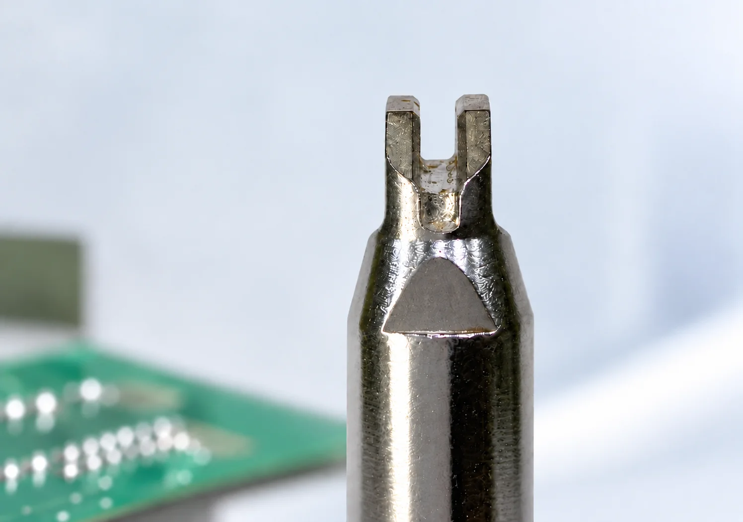
The automated applications shown here use special HAKKO K-series soldering tips with a groove or concave recess. These differ from the classic K-shape and expand the range of possibilities, particularly in situations where, in addition to heat transfer, solder needs to be kept available within the tip’s working area.

As a result, this tip geometry is suitable for a variety of applications. Examples range from terminal blocks and connectors to microswitches and ultrasonic sensors.

The application determines the geometry and dimensions of the K-shape

Not every solder joint places the same demands on a soldering tip. The spacing between connections, component geometry, accessibility, heat requirements, and the method of solder delivery can vary significantly in some cases.

HAKKO therefore offers various tip variants with grooves for automated soldering processes. In the HAKKO product line, these are designated as K-shape with groove.

The recess plays an important role in this process. It allows solder to be collected near the tip of the soldering iron and held in place for the actual connection. Depending on the application, this can be used both for guided movements along multiple connections and for individual solder joints.

It is not just the K-geometry that is crucial. The width and depth of the groove, as well as the external dimensions, must also be suitable for the specific soldering task.

Soldering Terminal Strings with Consistent Automation

A typical application involves closely spaced rows of connections. In this case, multiple contacts must be heated in a reproducible manner and supplied with solder.

For the LCD connections shown in the HAKKO application example, a K-tip with a groove is guided along the contacts. The solder held in the groove can be transferred to the individual solder joints during this movement.

To ensure a stable process, the tip geometry and motion must be matched to the connection row. Factors to consider include:

  • Spacing and geometry of the connections
  • Width of the soldering tip and the groove
  • Contact surface at the solder joint
  • Heat demand
  • Travel speed
  • Available soldersize

In this case, drag soldering is the appropriate process strategy. The focus, however, is on the application in which a series of contacts is soldered as part of a reproducible, automated process.

Processing Different Connectors with Matching Tip Widths

Connectors also illustrate why the design of the K-shape is crucial. In the application example shown, a wider tip variant is used for a dual-row connector. This allows the tip geometry to be adapted to the width and arrangement of the contacts.

Another example is the soldering of an SMD connector using a narrower version.

This highlights an important principle of automated soldering technology: There is no single tip width that is suitable for all connectors. The dimensions must match the actual terminal geometry.

A wider tip can offer advantages depending on the contact configuration. However, if it is too large for the existing solder joint, accessibility and the distance to adjacent structures can become problematic. Conversely, a tip that is too small can make it difficult to establish the desired contact or apply solder.

The various examples demonstrate how different dimensions within the same tip family can be specifically adapted to the respective application.

Soldering a microswitch with a K-type soldering tip with a groove

Its range of applications is not limited to long chains of connections.

In the case of a microswitch, the second HAKKO application example demonstrates how the groove in the tip can also be used on a single, spatially limited solder joint. Solder can be held in the groove. The soldering tip is then positioned against the connection so that the required heat and solder can be transferred to the joint.

In such applications in particular, the geometry and position of the solder joint are critical. The groove must match the shape of the terminal, while at the same time ensuring reliable contact between the areas to be soldered.

This example illustrates that the K-shape is not intended exclusively for drag soldering processes. Its unique geometry can also offer advantages for individual connection points.

Soldering ultrasonic sensors using a defined tin bath

Another example of its use is soldering an ultrasonic sensor.

Here, the groove in the soldering tip is used to create a small pool of solder near the tip. This solder is then immediately available at the soldering joint.

For process design, it is crucial that both the solder bath and the contact with the solder joint are reproducible. The tip position, heat transfer, solder volume, and contact time must therefore be tailored to the specific terminal geometry.

This example illustrates particularly clearly that, in an automated process, a soldering tip can do more than just transfer heat. Its geometry can also influence how solder is picked up, held, and applied to the solder joint.

Why the groove is crucial in the K-shape

The distinctive feature of the K-tips used in automated applications is their groove or concave recess.

The groove allows solder to be held within the tip's working area and kept ready for the soldering process. Depending on the soldering task, this solder can then be applied as the tip moves along a series of connections or specifically to a single joint.

However, the amount of solder actually required cannot be determined solely by the size of the groove. Solder diameter, solder feed, joint geometry, temperature, contact time, and process movement also influence the result.

The recess is therefore not a substitute for a defined process design. Rather, it expands the possibilities for precisely directing the flux and heat to the solder joint for specific applications.

D-shaped and K-shaped soldering tips meet different requirements

The D-shape, the classic K-shape, and the K-tips used for the automated applications shown have different geometries and, consequently, different primary applications.

The D-shape offers a flat contact surface and is suitable for, among other things, individual connections, larger solder pads, wires, and spot and drag soldering processes. The K variants shown here, on the other hand, feature a groove or concave recess. This allows solder to be collected in the tip’s working area and held ready for the soldering process. This enables applications on terminal blocks, connectors, switches, or sensor terminals.

Which tip shape is more suitable depends on the specific solder joint and the planned process.

Applications of the D-form
Learn more about the applications of the D-shape in automated soldering

Selecting the Right K-Type Tip for the Automated Soldering Process

The application examples shown illustrate just how varied the requirements for a soldering tip can be. An LCD pin header has different requirements than a two-row connector, a microswitch, or an ultrasonic sensor.

Therefore, the following factors in particular should be taken into account when making a selection:

  • Geometry and dimensions of the solder joint
  • Number and arrangement of connections
  • Accessibility
  • Required contact area
  • Heat demand of the connection
  • Required amount of solder
  • Type of solder feeding
  • Sequence of movements
  • Process and cycle time
  • Positioning and component tolerances

Only by considering these criteria together can one determine which tip geometry and dimensions are suitable for the specific application.

HAKKO offers a variety of K-tips with different groove and outer dimensions for automated soldering processes. This allows the tip to be specifically tailored to the respective terminal geometry and process requirements.

Hakko robotic soldering unit
Learn more about the Hakko FU-500/FU-601 robotic soldering unit here:

From the Application to the Right Soldering Tip

The examples shown make it clear that the choice of a K-tip with a groove cannot be determined solely by asking, „Spot soldering or drag soldering?“.

The most important factor is the application.

If multiple connections need to be processed as part of a continuous motion, drag soldering may be the appropriate process. In the case of a microswitch or ultrasonic sensor, however, it may be advantageous to keep solder in the groove and apply it precisely to a single solder joint.

The wide selection of different HAKKO soldering tips makes it possible to tailor these parameters specifically to each automated soldering task.

We'd be happy to advise you on selecting the right HAKKO soldering tips for your automated soldering processes