
FAQs

Key factors include the size and geometry of the solder joint, thermal mass, accessibility, and the required contact area. Cycle time and process stability should also be taken into account. The D-shape must transfer sufficient heat without affecting adjacent components or structures.
A properly sized D-shape promotes uniform heat transfer thanks to its defined contact surface. In automated production processes, this can contribute to reproducible soldering conditions. The interplay between temperature, contact time, solder feed, and motion sequence remains critical.

Yes. Soldering tip type D can be used for both individual spot soldering and trace soldering processes. In spot soldering, the tip is precisely positioned at a solder joint; in drag soldering, it is guided along several suitable terminals. Which method is appropriate depends on the component geometry, terminal arrangement, and process requirements.

More about the differences between the two methods can be found in the article spot soldering vs. drag soldering in robotic soldering.

Due to its flat geometry, a D-shaped tip can provide a larger contact area with the solder joint than a very fine conical tip. This allows heat to be efficiently transferred to the pad, terminal, or wire. However, the soldering tip should not be larger than is necessary for the specific solder joint.

The D-shape is suitable, among other things, for soldering chip components, larger pads, and leads, as well as for spot and drag soldering processes. Wires and various terminal geometries can also be processed using a properly sized chisel-shaped tip. It is crucial that the width and contact area of the soldering tip match the respective solder joint.

Chisel-shaped soldering tip for versatile applications in automated soldering

In automated soldering, the quality of the process is not determined solely by the robot program. The soldering tip must also be suitable for the specific solder joint. Its shape determines how heat is transferred, what contact area is available, and how the solder joint can be approached.

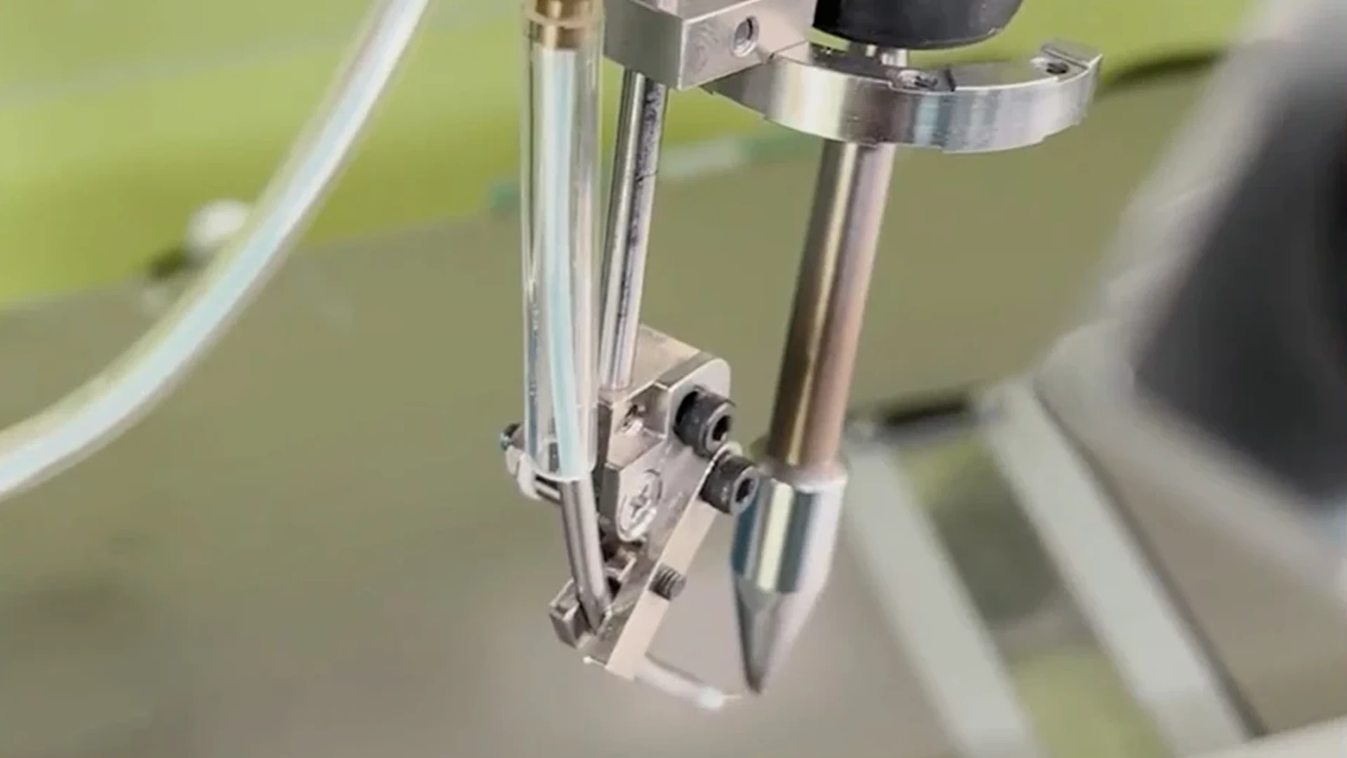
The HAKKO Type D soldering tip, often referred to as a chisel tip, is one of the most versatile tip geometries. Thanks to its flat shape, it can create a large contact area with the solder joint, depending on the selected width. This makes it suitable for a variety of applications, ranging from spot soldering on terminals and larger pads to drag soldering processes on evenly spaced contacts.

This highlights an important principle, particularly in robotic soldering: what matters is not having the finest possible soldering tip, but rather a tip geometry that is suited to the specific application and the heat requirements of the solder joint.

The soldering task determines the appropriate D-shape

The D-shaped soldering tip resembles a small chisel or a flat screwdriver. Compared to a conical soldering tip, it can make contact with the solder joint over a larger surface area.

This contact surface is crucial for heat transfer. The better the soldering tip makes contact with the pad, terminal, or wire, the more efficiently the required heat can be applied.

However, this does not mean that the largest possible D-shape is automatically the best choice. The dimensions of the soldering tip must be appropriate for the solder joint. A contact area that is too small can slow down the heating process. Conversely, a tip that is too large can damage adjacent components or structures.

The following factors, in particular, are therefore relevant to the selection process:

  • size and geometry of the solder joint
  • thermal mass of the component and the printed circuit board
  • accessibility of the solder joint
  • required contact area
  • type of soldering motion
  • required processing time

This makes the selection of the soldering tip an integral part of the process design.

Spot soldering on terminals and larger solder joints

A typical application of the D-shape is spot soldering on connectors, terminals, and larger solder pads.

For THT solder joints, the component terminal and the solder pad must be sufficiently heated so that the solder can wet the surfaces to be joined and flow into the metallized through-hole. The flat D-shape provides a large contact area for this purpose. This allows heat to be efficiently transferred to the component lead and the solder pad. This is particularly relevant for solder joints that require more heat due to their dimensions or thermal mass.

This is particularly relevant for solder joints that require more heat due to their dimensions or thermal mass. The D-shape can also demonstrate its strengths with connectors and similar connection geometries. The soldering tip can be precisely positioned at the contact point while simultaneously providing a sufficiently large heat transfer area.

This application example illustrates why the automation of a soldering process should always be considered from the perspective of the solder joint. Only when the geometry, heat input, solder feed, and motion sequence are properly aligned can a stable process be established.

Drag soldering with the D-shape

The D-shape can be used for more than just individual solder joints. Its geometry is also suitable for drag soldering processes, in which the soldering tip is guided along multiple terminals. Instead of processing each solder joint completely separately, suitable rows of terminals can be soldered in a single, defined motion.

This requires a solder joint geometry that allows the soldering tip to move in a controlled manner along the terminals. At the same time, sufficient heat transfer must be maintained during the movement.

The wide contact surface of the chisel-shaped tip can facilitate this process. However, the specific tip width, the arrangement of the connections, the flow of solder, and the speed of the soldering motion remain critical factors.

Spot soldering and drag soldering
Learn more about the differences between spot soldering and drag soldering in robotic soldering

Soldering wires and terminal connections using the chisel-shaped tip

The applications of the D-shape are not limited to printed circuit boards and terminal blocks. The larger contact area can also be put to good use in cables and various types of connectors.

When pre-tinning a wire, the soldering tip is positioned so that sufficient heat can be transferred to the wire. As the tip is moved in a controlled manner, solder is applied and distributed over the intended area.

A similar principle applies to connection or cup terminals. In this case, both the wire and the terminal must be sufficiently heated at the same time before the solder is applied. Uniform heat transfer to both parts being joined is crucial.

The D-shape can also offer advantages for grid- or cross-shaped connections. Such geometries pose special challenges for positioning and contact during automated soldering. Thanks to its flat contact surface, the D-shape can make precise contact with the wire or terminal to be soldered during the soldering process, thereby supporting a reproducible process.

It is precisely these types of applications that highlight the advantage of a tip shape tailored to the solder joint. The D-shape provides a defined surface area for heat transfer and can be positioned and guided in different ways depending on the soldering task.

The soldering tip as a key parameter in robotic soldering

In robotic soldering, positions, motion sequences, and process times are specified in a reproducible manner. For this reason, the geometry of the soldering tip must also be specifically tailored to the respective solder joint. It affects how well the solder joint makes contact and how effectively the required heat can be transferred.

An unsuitable tip shape cannot simply be compensated for by a higher temperature or a longer contact time. Therefore, when designing the process, the solder joint geometry, heat requirements, accessibility, and tip shape should all be considered together.

In the HAKKO robotic soldering system, the FU-500 handles the defined solder wire feed, while the FU-601 provides the required soldering power. The system supports both spot and drag soldering processes. The choice of soldering tip depends on the specific application and the geometric and thermal requirements of the solder joint.

Hakko robotic soldering unit
Learn more about the Hakko FU-500/FU-601 robotic soldering unit here: